 LadderCage
Vertical Access for Shafts & Stations
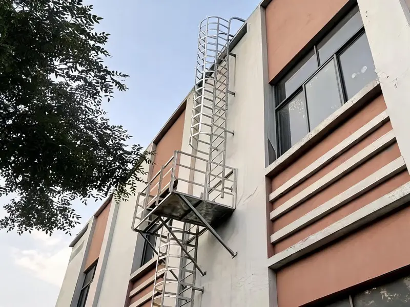
Elevator Shaft Cage Ladder
Vertical access for elevator shafts and lift stations; bolt-on install. Galvanized per ISO 1461; DoC with every shaft ladder.
Years Manufacturing
Countries Exported
Projects Delivered
Quote Response
Elevator Shafts & Lift Stations
Elevator Shaft Cage Ladder
Built for confined shaft spaces — elevator shaft inspection access and lift station maintenance access, delivered project-ready.
Elevator Shaft
Inspection and maintenance access for elevator pits and shafts, engineered to fit tight vertical envelopes.
Lift Station Cage Ladder
Maintenance access for pump stations and lift stations where durable, corrosion-resistant climbing is essential.
Engineered for Tight Shafts
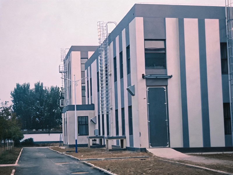
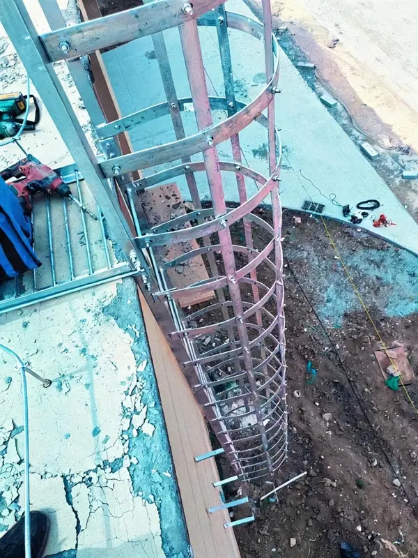
Elevator Shaft Cage Ladder Bolt-On Installation
Bolt-on install with drawings provided up front — engineered for tight shaft spaces so your contractor can pre-check clearances and fixing points before work starts.
- Bolt-On Sections
No on-site welding — faster, safer install in confined shafts
- Drawings Provided Up Front
Fixing points, clearances and section lengths before order
- Space-Restricted Design
Compact cage envelope sized to the shaft opening
Specifications & Dimensions
Elevator Shaft Cage Ladder Specifications
Engineered parameters for shaft and lift station vertical access, made-to-order.
Get My Shaft Project Quote| Specification | Value |
|---|---|
| Rung Diameter | Φ20 mm |
| Rung Spacing | 280 mm (≤300 mm) |
| Clear Width | 500 mm |
| Cage Diameter | Φ700 mm (hoops 40×5 @≤1500, straps 30×3) |
| Cage Start | 2.2 m above floor |
| Load Rating | 1.5 kN per rung |
| Material | Q235B HDG ISO 1461 85–100 μm; SS304 optional |
| Install | Bolt-on with drawings up front |
| Standards | OSHA 1910.28 · EN ISO 14122-4 |
Compliance & Documentation
Compliance & Documentation (OSHA / EN ISO 14122-4)
Galvanized per ISO 1461; DoC with every shaft ladder. MTC and structural calcs available for project submittal.
- DoC — OSHA 1910.28 & EN ISO 14122-4
Declaration of Conformity with every shaft ladder
- MTC 3.1 Material Certificate
Mill certs for Q235B HDG / SS304
- Structural Calculation Sheet
Engineer-signed for shaft project loads
Shaft & Station Packages, Factory-Direct
Get My Shaft Project Quote
Tell us the shaft dimensions, height, install environment and quantity — an engineer replies within 24 hours with installation drawings scope and a quote.
- 24h quote with drawings scope
- Bolt-on install, drawings up front
- DoC & ISO 1461 galvanizing included
Three Ways to Run a Ladder Up a Shaft
Inside a hoistway, the ladder is a guest in somebody else's geometry — guide rails, counterweights and divider beams got there first. The arrangement you choose determines whether the climb dodges that equipment for its whole height or borrows the shaft steel at set levels. Modernization crews pick the arrangement before anything else, because it decides section count, fixing points and how much of the shaft is occupied during the climb.
These are the three arrangements we fabricate for shaft and machine-room access.
| Arrangement | How It Works | Best For | Trade-Off |
|---|---|---|---|
| Straight run with side exits | One vertical line, step-through at each required level | Pit-to-machine-room climbs with clear wall | Needs unobstructed wall the whole height |
| Fold-back with returns | Two offset runs meeting at an intermediate landing | Narrow shafts, limited fall distance | More platforms and fixings to install |
| Split runs at divider beams | Sections anchored level by level to shaft steel | Modernizations working around rails | Longest install sequence of the three |
Site Walkthrough
A Shaft Access Ladder Measured to the Car Clearance
Lin is the modernization manager for a hospital elevator group. The 1960s hoistway ladders predate every current clearance rule, and the maintenance contractor refuses further climbs. Here is the replacement project from survey to sign-off.
With the car parked at top floor, Lin's elevator contractor measures pit depth, the clear dimension between car and shaft wall along the proposed climb line, guide rail bracket positions, and every landing sill projection. The ladder must clear the moving car by the code envelope, not by hope.
Our engineers plot brackets to miss rail brackets and sill plates, section joints at landing levels for access, and fold-back geometry where the pit is tight. One drawing set goes to the elevator contractor for clearance countersignature before production.
The car is locked out at a landing, and the trial-fitted sections go down the shaft bolted to the wall in sequence — no welding in the hoistway, no sparks near travelling cables. Sections sized for the door openings come through the landing entrances one by one.
With the car running full speed past every floor, clearances hold at each bracket. The contractor verifies rung spacing and cage geometry where required, files the MTC 3.1 and DoC, and the maintenance crew's next inspection climb is legal again.
| Survey Checklist (you bring) | Acceptance Checklist (you verify) |
|---|---|
| Pit depth and shaft clear width at climb line | Car passes every bracket at full speed |
| Guide rail bracket and sill positions per floor | Rung spacing 280 mm, width 500 mm verified |
| Landing door opening sizes for section entry | Sections entered without shaft cutting |
| Car lockout and install window plan | No hot work performed in hoistway |
| Contractor clearance rules | MTC 3.1, DoC filed with modernization record |
Decision Guide
Elevator Shaft Ladder Decisions: Choose This When…
Inside a hoistway, clearances and codes make the choices. Four forks settle the drawing.
| Decision | Choose X when… | Choose Y when… |
|---|---|---|
| Cage or no cage | Caged run — open shafts and older hoistways where the climb rides an exposed face | Uncaged run with fall-protection provision — fully enclosed modern shafts where the cage would foul the car clearance envelope |
| Top geometry | Straight run exiting at machine room floor — wide shafts with generous headroom | Fold-back top — narrow pits where the last rungs turn away from the shaft wall so the climber tops out protected |
| Material | HDG per ISO 1461 (85–100 μm) — dry, ventilated hoistways in office buildings | SS304 — hydraulic pits, persistent damp, or hospital shafts washed during service |
| Scope | One prototype shaft first — prove the bracket pattern, then replicate across the group | Whole portfolio order — volume tiers from 10 units across all shafts with one drawing family |
The mistake that stops a modernization program
- The mistake: ordering a standard wall ladder for the shaft without the car clearance envelope, figuring the bracket spacing "can be adjusted on site".
- The consequence: the car strikes a bracket at speed during the test run, the modernization fails acceptance, and the fix happens inside an occupied building with the elevators already handed over late.
- The correct move: send the shaft sections and the contractor's clearance rules — we draw bracket-by-bracket, the elevator contractor countersigns the drawing before production, and the calculation sheet comes free with the quote.
What You Get
Shaft Ladder Features, Translated to Modernization Outcomes
What each engineering line is worth inside an occupied building.
| Feature | Advantage | Your Outcome |
|---|---|---|
| Contractor-countersigned drawings | clearance verified before steel cuts | acceptance test passes first run |
| Door-sized bolted sections | enter through landing openings | no shaft cutting in an occupied building |
| No-weld hoistway install | no sparks near travelling cables | fire risk eliminated on install night |
| Fold-back pit geometry option | climber tops out facing away from wall | pit egress meets contractor rules |
| Damp-shaft SS304 option | hydraulic pits and wash-down service | the ladder outlives the modernization cycle |